5-29
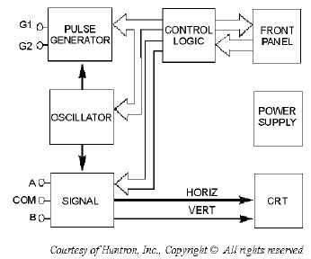
Figure 5-25.—Tracker 2000 block diagram.
Control Logic
The control logic senses which button is pushed on the front panel. Since the buttons are the
momentary action type, the logic must remember what button was pushed, turn on the LED indicator
within the button, and activate the appropriate configuration of the oscillator, signal, and pulse generator
sections.
After a button is pushed, the unit will remain in that configuration until another selection is made or
the power is secured. The HIGH LOCKOUT and PULSE GENERATOR push buttons are the only ones
that require repetitive pressing to be turned on or off.
The channel relay is controlled by CHANNEL buttons A, ALT, and B. The relay is a single-pole,
double-throw type and is de-energized for channel A and energized for channel B. If CHANNEL A is
already selected and the CHANNEL B button is pressed, CHANNEL A will be canceled and CHANNEL
B selected. When the ALT button is pressed, another control line is set, which enables an internal clock to
toggle the channel relay on and off, causing the unit to alternate between channels A and B.
The internal clock is controlled by the RATE control knob on the front panel. When the ALT mode
is active, the LEDs within the A and B buttons flash alternately, and the ALT LED is on continuously.
Pressing either of the channel buttons will cancel the ALT mode, and the selected channel will then
become active.
The FREQUENCY buttons (50/60, 400, and 2000 Hz) directly control the operation of the oscillator
and the pulse generator. The RANGE buttons (LOW, MED 1, MED 2, and HIGH) control four relays in
the signal section that select the appropriate terminal characteristics for each impedance range (table 5-4).


