5-30
Table 5-4.—Terminal Characteristics for Impedance ranges
RANGE
OPEN CIRCUIT
VOLTAGE (Vp)
SHORT CIRCUIT
CURRENT (mAr)
High
60
0.57
Medium 2
20
0.53
Medium 1
15
8.5
Low
10
132
You can select the four ranges manually by pressing the RANGE button, or you can scan them
automatically by using the AUTO function. When AUTO is activated, the control logic will follow the
sequence LOW, MED 1, MED 2, and HIGH over and over if HIGH LOCKOUT is off. The current active
range is always indicated by the LED for the range selected. The AUTO mode will stay active until you
select a particular range by pressing its associated button. While AUTO is active, the AUTO LED is
continuously on.
The speed at which the ranges are scanned is controlled by the front-panel RATE control knob. This
allows you to adjust the time each range is displayed for signature analysis on the CRT display. If AUTO
and ALT (alternate) are active at the same time, the RATE control affects the speed of both functions
with ALT having priority. This is done so that the two channels can be compared to each other within one
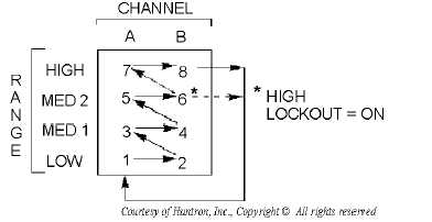
range before the next range is selected (figure 5-26).
Figure 5-26.—Range scanning sequence with AUTO and ALT active.
The HIGH LOCKOUT function disables the HIGH range and limits the maximum test signal to 20
volts peak vice 60 volts peak. When you select the manual mode (AUTO off), activating the HIGH
LOCKOUT prevents the HIGH range from being selected. If the HIGH range is active when the HIGH
LOCKOUT is pressed, the HIGH range is canceled and the next lower range (MED 2) will be selected
and become active. When you select the AUTO mode, the RANGE sequence with the HIGH LOCKOUT
active will start with LOW, and sequence through MED 1, MED 2, back to LOW, and continue until the
AUTO mode is stopped.
The PULSE GENERATOR buttons (positive [+], negative [-], and PULSE/DC) toggle control lines
that change the polarity and output type of the pulse generator.


