5-26
The AUTO feature, when selected, will allow the unit to automatically scan through the four ranges
at a speed set by the technician using the RATE control knob. This allows the user to keep his or her
hands free to hold test leads while still being able to observe the component under test signature for
analysis. The HIGH LOCKOUT, when selected by the technician, prevents the unit from functioning in
the HIGH range in either the manual or AUTO mode.
Channel Selection
You can select two channels by pressing the channel A (test probes connected to A jack and COM)
or channel B (test probes connected to B and COM jacks) push button on the front panel. When using a
single channel, you should plug the red probe into the corresponding channel test jack, and plug the black
test lead into the common test jack. When testing a component, you should connect the red probe to the
positive terminal and the black probe to the negative terminal of the component under test. Following this
procedure every time will ensure that the signature for the component under test will be displayed in the
correct quadrants of the CRT display.
The ALT (alternate) mode provides automatic switching back and forth between channel A and
channel B. This allows you to easily compare two components or the same test points on two circuit
boards. You select the ALT mode by pressing the ALT push button on the front panel. The rate of
switching between channels A and B can be varied by adjusting the RATE control knob on the front
panel. You will find that the ALT mode feature is very useful for comparing a known good component
with the same type of component that is of unknown quality.
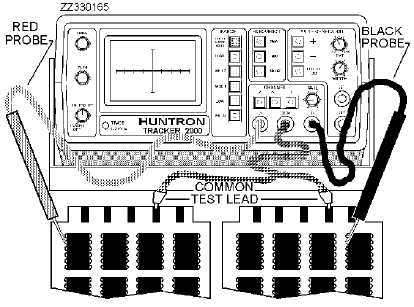
Figure 5-21 shows a typical way of connecting the unit to a known good circuit board and a board
under test. This test mode uses the supplied common test leads to connect two equivalent points on the
boards to the common test jack. Note that the black probe is now being used in the channel B jack rather
than the COM jack. When the technician uses the ALT and AUTO features together, each channel is
displayed before the range selection will change. Figure 5-22 shows the sequence of these changes.
Figure 5-21.—ALT (alternate) mode setup.