5-24
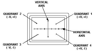
Figure 5-19.—CRT display.
Quadrant 1 displays positive voltage and positive current.
Quadrant 2 displays negative voltage and positive current.
Quadrant 3 displays negative voltage and negative current.
Quadrant 4 displays positive voltage and negative current.
Q-8. On the CRT display, what information is displayed in Quadrant 4?
The horizontal axis (see figure 5-19) is divided into eight equal divisions, allowing the technician to
estimate the voltage at which changes occur in the signature for the component being tested. The
associated approximate horizontal sensitivities for each range are:
High = 15.0 Volts/Div.
Medium 2 = 5.0 Volts/Div.
Medium 1 = 3.75 Volts/Div.
Low = 2.5 Volts/Div.
Back Panel
The back panel (figure 5-20) provides three additional controls and connectors. One is the accessory
output connector (ACC), which provides a clock signal and power for the Huntron Switcher Model
HSR410. Next, is the power cord connector used to provide the required ac line voltage used to power the
unit. The last item found on the back panel is the FOCUS control; this controls the focus for the front-
panel CRT display.


