5-21
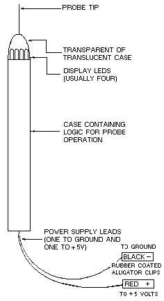
Figure 5-17.—Basic logic probe.
The logic probe can be powered from the supply of the circuit under test or from a regulated dc
power supply. If a separate power supply is used, the ground points of the power supply and circuit under
test should be connected together.
The display LED (light-emitting diode) near the probe tip provides an immediate indication of the
logic state existing in the circuit under test. The LED will provide any of four indications: (1) off, (2) dim
(about one-half brilliance), (3) bright (full brilliance), and (4) flashing on and off. The LED is normally in
the dim state and must be driven to one of the other three states by voltage levels at the probe tip. The
LED is usually bright for inputs above the logic "1" threshold and off for inputs below the logic "0"
threshold. The LED is usually dim for voltages between the logic "1" and logic "0" thresholds and for
open circuits.
Q-7. The LED lamps of a typical logic probe are normally in what state?
Another logic circuit analysis technique is useful with the logic probe. This technique is to run the
circuit under test at its normal clock (timing) rate while monitoring for various control signals, such as
RESET, START, STOP, SHIFT, TRANSFER, or CLOCK. Questions such as "Is the counter operating?"
are quickly resolved by noting if the probe indicator is flashing on and off, indicating that pulse train
activity is present.
This ends our discussion on logic probes. Now, we'll study another piece of electronics test
equipment that is used in evaluating integrated circuits, the HUNTRON TRACKER 2000.


