5-22
HUNTRON TRACKER 2000
The logic probe we just discussed is but one specialized tool used to isolate problems to the
component level. Another device you can use is the Huntron Tracker 2000. It is a very versatile electronic
troubleshooting tool that is used to evaluate suspect components and/or locate defective components on
de-energized circuit cards quickly and safely without requiring the removal of component leads. The unit
provides a built-in display that allows you to visually analyze the component under test conditions.
CAUTION
Before connecting the Huntron Tracker 2000, you must first secure all power,
then discharge all high-voltage capacitors.
PHYSICAL FEATURES
Because the Tracker 2000 has so many controls and indicators, it would impractical to cover each
within this chapter. We will therefore concentrate our discussion only to the externally accessible
features. To find information on internal controls and indicators, you should review the most current
technical manual with up-to-date changes entered for the unit being used.
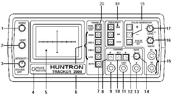
Front Panel
The front-panel (figure 5-18) design allows you to easily select the desired function. All the push
buttons are the momentary action type and have light-emitting diode (LED) indicators embedded in them
to show the functions that are active, by lighting up when active. A detailed description of each item on
the front panel is provided in table 5-3.
Figure 5-18.—Front Panel.