5-18
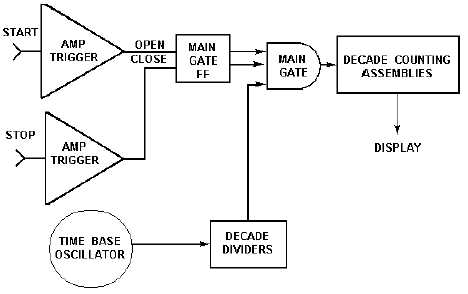
Figure 5-14.—Basic elements of a time interval counter.
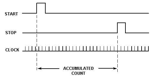
Figure 5-15.—Clock pulses.
Resolution
The resolution of the measurement is determined by the frequency of the counted clock (for
example, a 10-MHz clock provides 100 ns resolution [see figure 5-10, FREQUENCY RESOLUTION, N
selection switch]). The input amplifier, main gate, and DCAs (elements of the time interval counter) must
operate at speeds consistent with the clock frequency; otherwise the instrument's resolution would be
meaningless. Clock frequencies of 1, 10, and 100 MHz, and other 10n frequencies, are preferred, since the
accumulated count, with the appropriate placement of the decimal point, gives a direct readout of the time
interval. This explains why the conventional time interval counter is presently limited to 10 nanoseconds,
a clock frequency of 100 MHz. One GHz is beyond reach, and a clock frequency of 200 MHz would
require some arithmetic processing of the accumulated count in the DCAs to enable time to be displayed
directly.