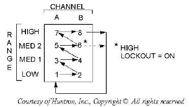
5-27
Figure 5-22.—AUTO/ALT sequence.
Frequency Selection
There are three test signal frequencies (50/60 Hz, 400 Hz, and 2000 Hz) that can be selected and then
provided by pressing the appropriate front-panel push button. During most troubleshooting evolutions, the
50/60 Hz test signal is the best to start with. The 400 Hz and 2000 hz frequencies are generally used to
view small amounts of capacitance or large amounts of inductance.
Pulse Generator
A built-in pulse generator is also provided with the Tracker 2000. It allows the technician to do
dynamic, in-circuit testing of certain devices in their active mode. In addition to using the red and black
probes, you can connect the output of the pulse generator to the control input of the device to be tested
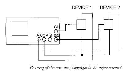
with one of the blue micro clips provided with the unit. The pulse generator has two outputs (G1 and G2
jacks) so that three devices can also be tested in the ALT (alternate) mode. Figure 5-23 shows a way of
connecting the unit in the ALT mode using the pulse generator.
Figure 5-23.—Pulse generator comparison mode.
There are a variety of output waveforms available using the pulse generator selection buttons, as
shown in figure 5-24. First, the technician must select the PULSE mode or DC mode using the
PULSE/DC button located on the front panel. In the PULSE mode, the PULSE/DC LED flashes at a slow
rate. While in the DC mode, this LED will be continuously on.