5-17
Period Measurement
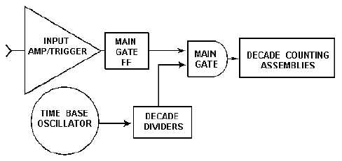
Period, the inverse of frequency, can be measured with the counter by reversing the inputs to the
main gate. With the FUNCTION selector switch in the PER A position, the input signal controls the
duration over which the main gate is open and the decade divider output is counted by the DCAs (see
figure 5-13). The duration of the count is one cycle or period of the input signal. When the FUNCTION
selector is in the PER AVG A position, the unused decades in the decade divider chain are used to divide
the amplifier/trigger output so that the gate remains open for decade steps of each input period rather than
a single period. This is the basis for multiple period averaging. Period and period averaging techniques
are used to increase measurement accuracy on low-frequency measurements.
Figure 5-13.—Measuring period.
Ratio Measurement
Placing the FUNCTION selector switch to RATIO C/A OR B/A sets the counter to measure the ratio
of the signal frequency at channel C or B to the signal frequency at channel A. Using the same
configuration as in figure 5-13 and replacing the time base with a second input frequency, f2, you can
measure the ratio of f
2/f. The signal at frequency f can be divided into decade steps in the same manner as
multiple period averaging for higher resolution.
Time Interval Measurement
Figure 5-14 illustrates the configuration for the measurement of time between two events or time
interval. This is done by placing the FUNCTION selector in the T.I.AVG AB position. The START input
opens the main gate, and the STOP input closes it. The START input is applied to channel A, and the
STOP input is applied to channel B. The decade divider output (clock pulses) is counted, and the display
shows the elapsed time between START and STOP signals, as shown in figure 5-15.


