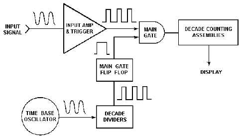
5-16 Frequency Measurement As discussed previously, the model 5328A frequency counter is capable of measuring frequency, time period (inverse of frequency), ratio, and time interval. We will start with frequency. When the FUNCTION selector is in the FREQ A or FREQ C position, the counter measures the frequency, f, by accumulating the number of cycles, n, of the input signal that occurs over the time period, t. This is expressed by: The basic counter elements necessary to perform this measurement are shown in figure 5-12. The INPUT AMPLIFIER/TRIGGER essentially conditions the input signal to a format that is compatible with the internal circuitry of the counter. As figure 5-12 indicates, the output of the amplifier/trigger corresponds directly to the input signal. Figure 5-12.—Basic elements of the frequency counter. The TIME BASE OSCILLATOR is a 10-MHz temperature-controlled (oven-regulated) precision, crystal oscillator used for the time base element from which time, t, is derived. DECADE DIVIDERS take the time base oscillator signal as the input and provide a pulse train, whose frequency is variable in decade steps. This frequency can be controlled by the FREQ RESOLUTION, N switch. The time, t, is determined by the period of this pulse train. The heart of the counter is the MAIN GATE. When the gate is opened, pulses from the amplifier/trigger are allowed to pass through. The opening and closing of the main gate is controlled by the decade divider output to the main gate flip-flop. The output of the MAIN GATE is then sent to the DECADE COUNTING ASSEMBLIES (DCAs), where the pulses are combined and displayed after the gate is closed. If the FREQUENCY RESOLUTION, N selection switch, is set for 106, the main gate is open for 1 second, and the decade counting assemblies display the frequency of the input signal in hertz (refer to figure 5-10, FREQUENCY RESOLUTION, N selection switch).
Integrated Publishing, Inc. - A (SDVOSB) Service Disabled Veteran Owned Small Business