5-11
The output circuit of the rf signal generator usually contains a calibrated attenuator and an output
level meter. The output level meter provides an indication and permits control of the output voltage of the
generator. The attenuator allows you to select the amount of this output. The attenuator is made up of a
group of resistors that form a voltage-dropping circuit.
It is controlled by a control calibrated in microvolts. When the control is adjusted so that the output
meter reads unity (1.0), the reading on the attenuator control gives the exact value (no multiplication
factor) of the output in microvolts. If an output voltage at a lower value is desired, the attenuator control
is varied until the meter indicates some decimal value less than 1. This decimal is multiplied by the
attenuator reading to give the actual output in microvolts.
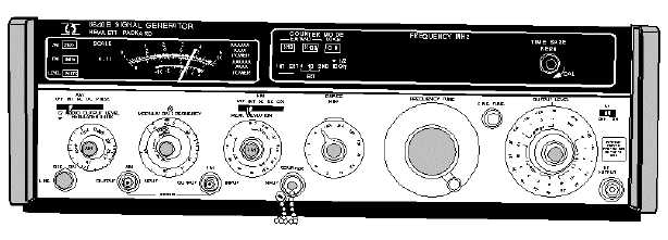
An rf signal generator currently in wide use by the Navy is the HP 8640B (figure 5-8). The HP
8640B signal generator covers the frequency range of 500 kilohertz to 512 megahertz, and can be
extended to 1,024 MHz by using adapters.
Figure 5-8.—Rf signal generator (HP-model 8640B).
This completes our discussion of signal generators. The following section deals with an instrument
that measures frequency—the FREQUENCY COUNTER.
FREQUENCY COUNTERS
The signal generators you studied in the previous section provide signals for use in testing, aligning,
and troubleshooting electronic equipment. Now, we will study the FREQUENCY COUNTER, an
instrument that measures frequencies. Frequency counters are used to measure frequencies already in
existence. An example of a typical frequency counter, the model 5328A, is shown in figure 5-9.


