5-12
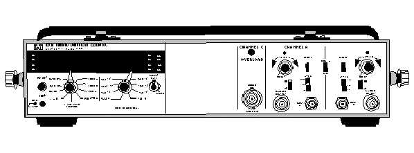
Figure 5-9.—Model 5328A 500 MHz universal frequency counter.
GENERAL DESCRIPTION OF THE FREQUENCY COUNTER
The following description is for the model 5328A counter only. Other counters use different
techniques to derive the displayed frequency. The outputs available vary from counter to counter. For
further information on other types of counters and their uses, refer to EIMB, Test Equipment, NAVSEA
0967-LP-000-0040.
The model 5328A is a portable, solid-state electronic frequency counter. It is used to precisely
measure and display, using a nine-digit LED readout, frequency, period, period average, time interval,
time interval average, and ratio of electronic frequency signals. This frequency counter can also provide a
1-MHz and 10-MHz output signal through the back-panel BNC.
Q-6. What frequencies are provided through the back-panel BNC?
The model 5328A frequency counter can be divided into four major internal subsections: the main
counter section, input section, power supply, and interface bus section. Additionally, two separate (front
panel) input channels provide for time interval measurements. Each channel has an attenuator, trigger
slope selector, level control, ac or dc coupling, and an oscilloscope marker output. A third input channel
is provided to allow the measurement of 30 MHz to 500 MHz with a maximum input of 5 volts rms with
a fused-protected connection.
Front-panel controls are provided for you to do the function selection, frequency resolution, sample
rate, and reset display. Also, a push-button control on the front panel allows the unit to be used in the
operational or standby mode (power applied to the crystal oven to eliminate warm-up). Rear-panel
connectors provide the gated output frequencies and an input for an external frequency standard. A
detachable front cover is used to store accessory cables and connectors.
Controls and Indicators
Figures 5-10 and 5-11 show all the front- and rear-panel operating controls and indicators. Refer to
tables 5-1 and 5-2 for a description of each of the numbered controls and connectors shown in figures 5-
10 and 5-11, respectively.


