5-31
Oscillator
The oscillator produces a constant amplitude, low distortion sine wave test signal. The frequency of
the test signal is programmable between one variable frequency (50/60 Hz), and two fixed frequencies
(400 Hz and 2000 Hz). The variable frequency depends on the input power line used for the Tracker
2000; a 50-Hz line produces a 50-Hz test signal, and a 60-Hz line produces a 60-Hz test signal. If a 400-
Hz power line is used, an 80-Hz test signal is provided. This versatility is built in to ensure you will
always have low, medium, and high frequencies to work with.
Signal Section
The signal section is considered to be the heart of the Tracker 2000. In this section, the signal from
the oscillator is applied across two terminals of a device being tested via the front-panel jacks.
The test signal causes a current to flow through the device and a voltage drop to occur across its
terminals. The current flow causes a vertical deflection of the trace on the CRT display, while the voltage
drop across the device causes a horizontal deflection of the trace on the CRT display. By combining
these, the current-voltage signature of the device being tested is displayed on the CRT.
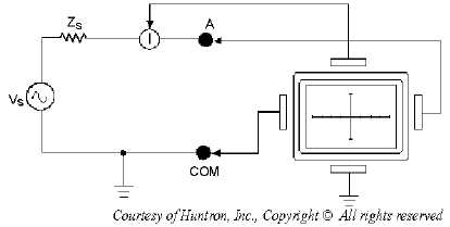
The test signal appears at the front-panel test jacks as though it is being originated by a voltage
source (Vs) with a series output impedance (Zs). An equivalent circuit of the signal section is shown in
figure 5-27. As you can see, the figure also shows how the terminal voltage affects the horizontal
deflection plates of the CRT, and how the current through the terminals affects the vertical deflection
plates through current sensing point I.
Figure 5-27.—Signal section equivalent circuit.
An open circuit has zero current flowing through the terminals and maximum voltage drop across the
terminals. In all ranges, this is represented by a straight horizontal trace from left to right on the CRT
display, as seen in figure 5-28 view A. When a short occurs, maximum current flows through the
terminals, and the voltage drop is considered to be zero. This occurs in all ranges and is represented by a
straight vertical trace from top to bottom of the CRT display, as seen in figure 5-28 view B.


