5-32
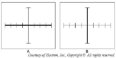
Figure 5-28.—Open and short circuit display.
Pulse Generator
The pulse generator provides dynamic testing for certain types of devices by driving the control input
of the device under test. The normal two-terminal mode of testing can be considered a static test, since
devices with three or more terminals are not tested in their active mode. However, with the pulse
generator, an in-circuit active test is possible.
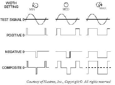
In the PULSE mode, this circuit uses the zero crossing of the test signal to trigger the start of the
pulse. When positive (+) is enabled, a positive-going zero crossing triggers a positive pulse. When
negative (-) is enabled, a negative-going zero crossing triggers a negative pulse. If both are enabled, then
both positive and negative pulses are produced on alternate crossings (composite pulses). Once a pulse is
triggered, its duration is set by the WIDTH control knob. Figure 5-29 shows the waveforms for three
pulse polarity types at various settings of the WIDTH control.
Figure 5-29.—Pulse generator waveforms.
The LEVEL control adjusts the peak of each pulse from zero to 5 volts with the polarity dependent
on the pulse polarity selected. When an open circuit is present, a maximum output of 5 volts peak-to-peak


