3-13
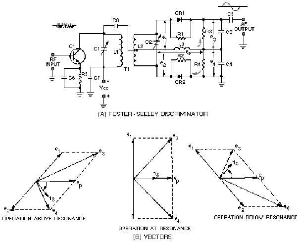
excessive amplitude variations from signals. The collector circuit tank consists of C1 and L1. C2 and L2
form the secondary tank circuit. Both tank circuits are tuned to the center frequency of the incoming fm
signal. Choke L3 is the dc return path for diode rectifiers CR1 and CR2. R1 and R2 are not always
necessary but are usually used when the back (reverse bias) resistance of the two diodes is different.
Resistors R3 and R4 are the load resistors and are bypassed by C3 and C4 to remove rf. C5 is the output
coupling capacitor.
Figure 3-11.—Foster-Seeley discriminator. FOSTER-SEELEY DISCRIMINATOR.
CIRCUIT OPERATION AT RESONANCE.—The operation of the Foster-Seeley discriminator
can best be explained using vector diagrams [figure 3-11, view (B)] that show phase relationships
between the voltages and currents in the circuit. Let's look at the phase relationships when the input
frequency is equal to the center frequency of the resonant tank circuit.
The input signal applied to the primary tank circuit is shown as vector ep. Since coupling capacitor
C8 has negligible reactance at the input frequency, rf choke L3 is effectively in parallel with the primary
tank circuit. Also, because L3 is effectively in parallel with the primary tank circuit, input voltage ep also
appears across L3. With voltage ep applied to the primary of T1, a voltage is induced in the secondary
which causes current to flow in the secondary tank circuit. When the input frequency is equal to the center
frequency, the tank is at resonance and acts resistive. Current and voltage are in phase in a resistance
circuit, as shown by is and ep. The current flowing in the tank causes voltage drops across each half of the
balanced secondary winding of transformer T1. These voltage drops are of equal amplitude and opposite

