3-11
detecting device must be constructed so that its output amplitude will vary linearly according to the
instantaneous frequency of the incoming signal.
Several types of fm detectors have been developed and are in use, but in this section you will study
three of the most common: (1) the phase-shift detector, (2) the ratio detector, and (3) the gated-beam
detector.
SLOPE DETECTION
To be able to understand the principles of operation for fm detectors, you need to first study the
simplest form of frequency-modulation detector, the SLOPE DETECTOR. The slope detector is
essentially a tank circuit which is tuned to a frequency either slightly above or below the fm carrier
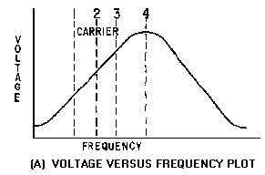
frequency. View (A) of figure 3-9 is a plot of voltage versus frequency for a tank circuit. The resonant
frequency of the tank is the frequency at point 4. Components are selected so that the resonant frequency
is higher than the frequency of the fm carrier signal at point 2. The entire frequency deviation for the fm
signal falls on the lower slope of the bandpass curve between points 1 and 3. As the fm signal is applied
to the tank circuit in view (B), the output amplitude of the signal varies as its frequency swings closer to,
or further from, the resonant frequency of the tank. Frequency variations will still be present in this
waveform, but it will also develop amplitude variations, as shown in view (B). This is because of the
response of the tank circuit as it varies with the input frequency. This signal is then applied to the diode
detector in view (C) and the detected waveform is the output. This circuit has the major disadvantage that
any amplitude variations in the rf waveform will pass through the tank circuit and be detected. This
disadvantage can be eliminated by placing a limiter circuit before the tank input. (Limiter circuits were
discussed in NEETS, Module 9, Introduction to Wave-Generation and Wave-Shaping Circuits.) This
circuit is basically the same as an AM detector with the tank tuned to a higher or lower frequency than the
received carrier.
Figure 3-9A.—Slope detector. VOLTAGE VERSUS FREQUENCY PLOT.
Figure 3-9B.—Slope detector. TANK CIRCUIT.


