3-8
provide an output that is proportional to the peak rf pulses. The filter offers a low impedance to rf and a
relatively high impedance to af. (Filters were discussed in NEETS, Module 9, Introduction to Wave-
Generation and Wave-Shaping Circuits.) This action causes C2 to develop the waveform in view (D).
This varying af voltage is applied to the headset which then reproduces the original modulating
frequency. This circuit is called a series-diode detector (sometimes referred to as a VOLTAGE-DIODE
DETECTOR) because the semiconductor diode is in series with both the input voltage and the load
impedance. Voltages in the circuit cause an output voltage to develop across the load impedance that is
proportional to the input voltage peaks of the modulation envelope.
Q-9.
What are the three requirements for an AM demodulator?
Q-10.
What does the simplest diode detector use to reproduce the modulating frequency?
Q-11.
What is the function of the diode in a series-diode detector?
Q-12.
In figure 3-5, what is the function of C2?
Shunt-Diode Detector
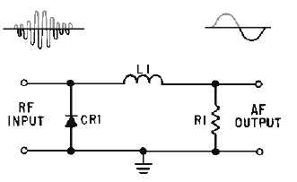
The SHUNT-DIODE DETECTOR (figure 3-6) is similar to the series-diode detector except that the
output variations are current pulses rather than voltage pulses. Passing this current through a shunt
resistor develops the voltage output. The input is an rf modulated envelope. On the negative half cycles of
the rf, diode CR1 is forward biased and shunts the signal to ground. On the positive half cycles, current
flows from the output through L1 to the input. A field is built up around L1 that tends to keep the current
flowing. This action integrates the rf current pulses and causes the output to follow the modulation
envelope (intelligence) closely. (Integration was discussed in NEETS, Module 9, Introduction to
Wave-Generation and Wave-Shaping Circuits.) Shunt resistor R1 develops the output voltage from this
current flow. Although the shunt detector operates on the principle of current flow, it is the output voltage
across the shunt resistor that is used to reproduce the original modulation signal. The shunt-diode detector
is easily identified by noting that the detector diode is in parallel with both the input and load impedance.
The waveforms associated with this detector are identical to those shown in views (B), (C), and (D) of
figure 3-5.
Figure 3-6.—Shunt-diode detector.
The series-diode detector is normally used where large input signals are supplied and a linear output
is required. The shunt-diode detector is used where the voltage variations are too small to produce a full
output from audio amplifier stages. Additional current amplifiers are required to bring the output to a
usable level. Other methods of detection and amplification have been developed which will detect low-


