3-3
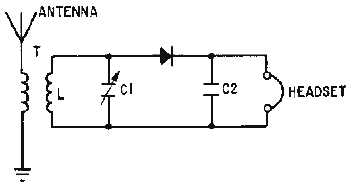
Figure 3-2.—Cw demodulator.
HETERODYNE DETECTION
The use of an af voltage in the detector aids the operator in distinguishing between various signals.
Since the carrier is unmodulated, the af voltage can be developed by using the heterodyne procedure
discussed in chapter 1. The procedure is to mix the incoming cw signal with locally generated
oscillations. This provides a convenient difference frequency in the af range, such as 1,000 hertz. The af
difference frequency then is rectified and smoothed by a detector. The af voltage is reproduced by a
telephone headset or a loudspeaker.
Consider the heterodyne reception of the code letter A, as shown in figure 3-3, view (A). The code
consists of a short burst of cw energy (dot) followed by a longer burst (dash). Assume that the frequency
of the received cw signal is 500 kilohertz. The locally generated oscillations are adjusted to a frequency
which is higher or lower than the incoming rf signal (501 kilohertz in this case), as shown in view (B).
The voltage resulting from the heterodyning action between the cw signal [view (A)] and the local
oscillator signal [view (B)] is shown in view (C) as the mixed-frequency signal. ENVELOPE
(intelligence) amplitude varies at the BEAT (difference) frequency of 1,000 hertz (501,000 - 500,000).
The negative half cycles of the mixed frequency are rectified, as shown in view (D). The peaks of the
positive half cycles follow the 1,000-hertz beat frequency.
Figure 3-3A.—Heterodyne detection. RECEIVED CW SIGNAL.
Figure 3-3B.—Heterodyne detection. LOCAL OSCILLATOR SIGNAL.


