3-10
COMMON-BASE DETECTOR
Another amplifying detector that is used in portable receivers is the COMMON-BASE DETECTOR.
In this circuit detection occurs in the emitter-base junction and amplification occurs at the output of the
collector junction. The output developed is the equivalent of a diode detector which is followed by a stage
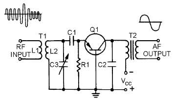
of audio amplification, but with more distortion. Figure 3-8 is a schematic of a typical common-base
detector. Transformer T1 is tuned by capacitor C3 to the frequency of the incoming modulated envelope.
Resistor R1 and capacitor C1 form a self-biasing network which sets the dc operating point of the emitter
junction. The af output is taken from the collector circuit through audio transformer T2. The primary of
T2 forms the detector output load and is bypassed for rf by capacitor C2.
Figure 3-8.—Common-base detector.
The input signal is coupled through T1. When capacitor C3 is tuned to the proper frequency, the
signal is passed to the emitter of Q1. When no input signal is present, bias is determined by resistor R1.
When the input signal becomes positive, current flows through the emitter-base junction causing it to be
forward biased. C1 and R1 establish the dc operating point by acting as a filter network. This action
provides a varying dc voltage that follows the peaks of the rf modulated envelope. This action is identical
to the diode detector with the emitter-base junction doing the detecting. The varying dc voltage on the
emitter changes the bias on Q1 and causes collector current to vary in accordance with the detected
voltage. Transformer T2 couples these af current changes to the output. Thus, Q1 detects the AM wave
and then provides amplification for the detected waveform.
The four AM detectors just discussed are not the only types that you will encounter. However, they
are representative of most AM detectors and the same characteristics will be found in all AM detectors.
Now let’s study some ways of demodulating frequency-modulated (fm) signals.
Q-18.
Which junction acts as the detector in a common-base detector?
Q-19.
To what circuit arrangement is a common-base detector equivalent?
Q-20.
In figure 3-8, which components act as the filter network in the diode detector?
FM DEMODULATION
In fm demodulators, the intelligence to be recovered is not in amplitude variations; it is in the
variation of the instantaneous frequency of the carrier, either above or below the center frequency. The


