3-16
the tank current is in phase with the primary voltage ep. The current flowing in the tank circuit causes
voltages e1 and e2 to be developed in the secondary winding of T1. These voltages are of equal magnitude
and of opposite polarity with respect to the center tap of the winding. Since the winding is inductive, the
voltage drop across it is 90 degrees out of phase with the current through it.
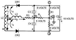
Figure 3-13 is a simplified schematic diagram of a ratio detector at resonance. The voltage applied to
the cathode of CR1 is the vector sum of e1 and ep. Likewise, the voltage applied to the anode of CR2 is
the vector sum of e2 and ep. No phase shift occurs at resonance and both voltages are equal. Both diodes
conduct equally. This equal current flow causes the same voltage drop across both R1 and R2. C3 and C4
will charge to equal voltages with opposite polarities. Let’s assume that the voltages across C3 and C4 are
equal in amplitude (5 volts) and of opposite polarity and the total charge across C5 is 10 volts. R1 and R2
will each have 5 volts dropped across them because they are of equal values. The output is taken between
points A and B. To find the output voltage, you algebraically add the voltages between points A and B
(loop ACB or ADB). Point A to point D is -5 volts. Point D to point B is + 5 volts. Their algebraic sum is
0 volts and the output voltage is 0 at resonance. If the voltages on branch ACB were figured, the same
output would be found because the circuit branches are in parallel.
Figure 3-13.—Current flow and polarities at resonance.
When the input signal reverses polarity, the secondary voltage across L2 also reverses. The diodes
will be reverse biased and no current will flow. Meanwhile, C5 retains most of its charge because of the
long time constant offered in combination with R1 and R2. This slow discharge helps to maintain the
output.
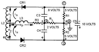
OPERATION ABOVE RESONANCE.—When a tuned circuit (figure 3-14) operates at a
frequency higher than resonance, the tank is inductive. The secondary current i
lags the primary voltage
ep. Secondary voltage e1 is nearer in phase with primary voltage e, while e2 is shifted further out of phase
with ep. The vector sum of e1 and ep is larger than that of e2 and ep. Therefore, the voltage applied to the
cathode of CR1 is greater than the voltage applied to the anode of CR2 above resonance.
Figure 3-14.—Current flow and polarities above resonance.


