3-17
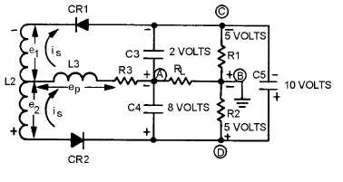
Assume that the voltages developed above resonance are such that the higher voltage on the cathode
of CR1 causes C3 to charge to 8 volts. The lower voltage on the anode of CR2 causes C4 to charge to 2
volts. Capacitor C5 remains charged to the sum of these two voltages, 10 volts. Again, by adding the
voltages in loop ACB or ADB between points A and B, you can find the output voltage. Point A to point
D equals -2 volts. Point D to point B equals +5 volts. Their algebraic sum, and the output, equals +3 volts
when tuned above resonance. During the negative half cycle of the input signal, the diodes are reverse
biased and C5 helps maintain a constant output.
OPERATION BELOW RESONANCE.—When a tuned circuit operates below resonance (figure
3-15), it is capacitive. Secondary current is leads the primary voltage ep and secondary voltage e2 is nearer
in phase with primary voltage ep. The vector sum of e2 and ep is larger than the sum of e1 and ep. The
voltage applied to the anode of CR2 becomes greater than the voltage applied to the cathode of CR1
below resonance.
Figure 3-15.—Current flow and polarities below resonance.
Assume that the voltages developed below resonance are such that the higher voltage on the anode of
CR2 causes C4 to charge to 8 volts. The lower voltage on the cathode of CR1 causes C3 to charge to 2
volts. Capacitor C5 remains charged to the sum of these two voltages, 10 volts. The output voltage equals
-8 volts plus +5 volts, or -3 volts, when tuned below resonance. During the negative half cycle of the
input signal, the diodes are reverse biased and C5 helps maintain a constant output.
Advantage of a Ratio Detector
The ratio detector is not affected by amplitude variations on the fm wave. The output of the detector
adjusts itself automatically to the average amplitude of the input signal. C5 charges to the sum of the
voltages across R1 and R2 and, because of its time constant, tends to filter out any noise impulses. Before
C5 can charge or discharge to the higher or lower potential, the noise disappears. The difference in charge
across C5 is so slight that it is not discernible in the output. Ratio detectors can operate with as little as
100 millivolts of input. This is much lower than that required for limiter saturation and less gain is
required from preceding stages.
Q-26.
What is the primary advantage of a ratio detector?
Q-27.
What is the purpose of C5 in figure 3-12?
GATED-BEAM DETECTOR
An fm demodulator employing a completely different detection principle is the GATED-BEAM
DETECTOR (sometimes referred to as the QUADRATURE DETECTOR). A simplified diagram of a


