3-18
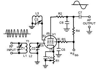
gated-beam detector is shown in figure 3-16. It uses a gated-beam tube to limit, detect, and amplify the
received fm signal. The output voltage is 0 when the input frequency is equal to the center frequency.
When the input frequency rises above the center frequency, the output voltage goes positive. When the
input frequency drops below the center frequency, the output voltage goes negative.
Figure 3-16.—Gated-beam detector.
Circuit Operation
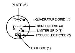
The gated-beam detector employs a specially designed gated-beam tube. The elements of this tube
are shown in figure 3-17. The focus electrode forms a shield around the tube cathode except for a narrow
slot through which the electron beam flows. The beam of electrons flows toward the limiter grid which
acts like a gate. When the gate is open, the electron beam flows through to the next grid. When closed, the
gate completely stops the beam.
Figure 3-17.—Gated-beam tube physical layout.
After the electron beam passes the limiter grid, the screen grid refocuses the beam toward the
quadrature grid. The quadrature grid acts much the same as the limiter grid; it either opens or closes the
passage for electrons. These two grids act similar to an AND gate in digital devices; both gates must be
open for the passage of electrons to the plate. Either grid can cut off plate current. AND gates were
presented in NEETS, Module 13, Introduction to Number Systems, Boolean Algebra, and Logic Circuits.
Look again at the circuit in figure 3-16. With no signal applied to the limiter grid (3), the tube
conducts. The electron beam moving near the quadrature grid (5) induces a current into the grid which
develops a voltage across the high-Q tank circuit (L3 and C3). C3 charges until it becomes sufficiently


