3-22
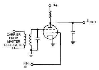
Figure 3-19.—Phase detector.
The modulated waveform is applied to the limiter grid. Gating action in the tube will occur as the
phase shifts between the input waveform and the reference. The combined output current from the gated-
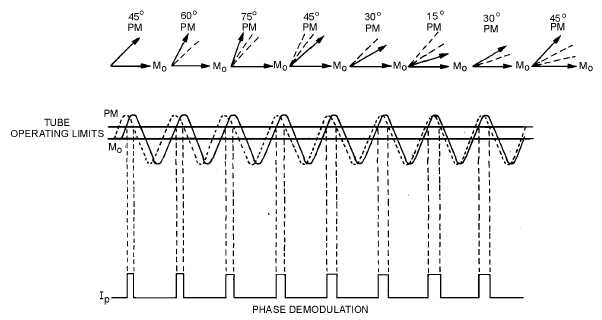
beam tube will be a series of current pulses. These pulses will vary in width as shown in figure 3-20. The
width of these pulses will vary in accordance with the phase difference between the carrier and the
modulated wave.
Figure 3-20.—Phase-detector waveforms.
Q-31.
Where is the intelligence contained in a phase-modulated signal?
Q-32.
Why can phase-modulated signals be detected by fm detectors?
Q-33.
How is a quadrature detector changed when used for phase demodulation?


