3-24
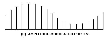
Figure 3-21B.—Peak detector. AMPLITUDE MODULATED PULSES.
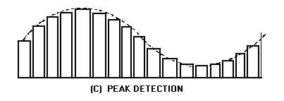
Figure 3-21C.—Peak detector. PEAK DETECTION.
Pulse-Duration Modulation
The peak detector circuit may also be used for pdm. To detect pdm, you must modify view (A) of
figure 3-21 so that the time constant for charging C1 through CR1 is at least 10 times the maximum
received pulse width. This may be done by adding a resistor in series with the cathode or anode circuit of
CR1. The amplitude of the voltage to which C1 charges, before being discharged by the negative pulse,
will be directly proportional to the input pulse width. A longer pulse width allows C1 to charge to a
higher potential than a short pulse. This charge is held, because of the long time constant of R1 and C1,
until the discharge pulse is applied to diodes CR2 and CR3 just prior to the next incoming pulse. These
charges across C1 result in a wave shape similar to the output shown for pam detection in view (C) of
figure 3-21.
Q-34.
In its simplest form, what functions must a radar detector be capable of performing?
Q-35.
What characteristic of a pulse does a peak detector sample?
Q-36.
What is the time constant of the resistor and capacitor in a peak detector for pam?
Q-37.
How can a peak detector for pam be modified to detect pdm?
LOW-PASS FILTER
Another method of demodulating pdm is by the use of a low-pass filter. If the voltage of a pulse
waveform is averaged over both the pulse and no-pulse time, average voltage is the result. Since the
amplitude of pdm pulses is constant, average voltage is directly proportional to pulse width. The pulse
width varies with the modulation (intelligence) in pdm. Because the average value of the pulse train
varies in accordance with the modulation, the intelligence may be extracted by passing the width-
modulated pulses through a low-pass filter. The components of such a filter must be selected so that the
filter passes only the desired modulation frequencies. As the varying-width pulses are applied to the low-


