3-15
RATIO DETECTOR
The RATIO DETECTOR uses a double-tuned transformer to convert the instantaneous frequency
variations of the fm input signal to instantaneous amplitude variations. These amplitude variations are
then rectified to provide a dc output voltage which varies in amplitude and polarity with the input signal
frequency. This detector demodulates fm signals and suppresses amplitude noise without the need of
limiter stages.
Circuit Operation
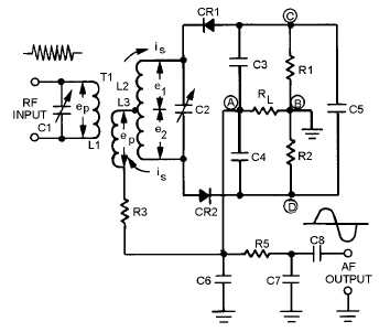
Figure 3-12 shows a typical ratio detector. The input tank capacitor (C1) and the primary of
transformer T1 (L1) are tuned to the center frequency of the fm signal to be demodulated. The secondary
winding of T1 (L2) and capacitor C2 also form a tank circuit tuned to the center frequency. Tertiary
(third) winding L3 provides additional inductive coupling which reduces the loading effect of the
secondary on the primary circuit. Diodes CR1 and CR2 rectify the signal from the secondary tank.
Capacitor C5 and resistors R1 and R2 set the operating level of the detector. Capacitors C3 and C4
determine the amplitude and polarity of the output. Resistor R3 limits the peak diode current and
furnishes a dc return path for the rectified signal. The output of the detector is taken from the common
connection between C3 and C4. Resistor RL is the load resistor. R5, C6, and C7 form a low-pass filter to
the output.
Figure 3-12.—Ratio detector.
This circuit operates on the same principles of phase shifting as did the Foster-Seeley discriminator.
In that discussion, vector diagrams were used to illustrate the voltage amplitudes and polarities for
conditions at resonance, above resonance, and below resonance. The same vector diagrams apply to the
ratio detector but will not be discussed here. Instead, you will study the resulting current flows and
polarities on simplified schematic diagrams of the detector circuit.
OPERATION AT RESONANCE.—When the input voltage ep is applied to the primary in figure
3-12 it also appears across L3 because, by inductive coupling, it is effectively connected in parallel with
the primary tank circuit. At the same time, a voltage is induced in the secondary winding and causes
current to flow around the secondary tank circuit. At resonance the tank acts like a resistive circuit; that is,

