1-15
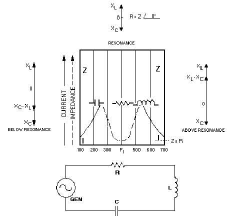
Figure 1-7.—Curves of impedance and current in an RLC series resonant circuit.
Note that the impedance curve does not reach zero at its minimum point. The vectors above and
below resonance show that the phase shift of the circuit at these frequencies is less than 90 degrees
because of the resistance.
The horizontal width of the curve is a measure of how well the circuit will pick out (discriminate) the
one desired frequency. The width is called BANDWIDTH, and the ability to discriminate between
frequencies is known as SELECTIVITY. Both of these characteristics are affected by resistance. Lower
resistance allows narrower bandwidth, which is the same as saying the circuit has better selectivity.
Resistance, then, is an unwanted quantity that cannot be eliminated but can be kept to a minimum by the
circuit designers.
More on bandwidth, selectivity, and measuring the effects of resistance in resonant circuits will
follow the discussion of parallel resonance.
Q-3. State the formula for resonant frequency.
Q-4. If the inductor and capacitor values are increased, what happens to the resonant frequency?
Q-5. In an "ideal" resonant circuit, what is the relationship between impedance and current?
Q-6. In a series-RLC circuit, what is the condition of the circuit if there is high impedance, low
current, and low reactance voltages?


