1-20
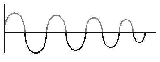
Figure 1-9.—Damped wave.
If it were possible to have a circuit with absolutely no resistance, there would be no heat loss, and the
oscillations would tend to continue indefinitely. You have already learned that tuned circuits are designed
to have very little resistance. Reducing I2R losses is still another reason for having low resistance.
A "perfect" tuned circuit would produce the continuous sine wave shown in figure 1-10. Its
frequency would be that of the circuit.
Figure 1-10.—Sine wave-resonant frequency.
Because we don't have perfection, another way of causing a circuit to oscillate indefinitely would be
to apply a continuous a.c. or pulsing source to the circuit. If the source is at the resonant frequency of the
circuit, the circuit will oscillate as long as the source is applied.
The reasons why the circuit in figure 1-8 oscillates at the resonant frequency have to do with the
characteristics of resonant circuits. The discussion of parallel resonance will not be as detailed as that for
series resonance because the idea of resonance is the same for both circuits. Certain characteristics differ
as a result of L and C being in parallel rather than in series. These differences will be emphasized.
Q-7. When the capacitor is completely discharged, where is the energy of the tank circuit stored?
Q-8. When the magnetic field of the inductor is completely collapsed, where is the energy of the tank
circuit stored?
PARALLEL RESONANCE
Much of what you have learned about resonance and series-LC circuits can be applied directly to
parallel-LC circuits. The purpose of the two circuits is the same — to select a specific frequency and
reject all others. XL still equals XC at resonance. Because the inductor and capacitor are in parallel,
however, the circuit has the basic characteristics of an a.c. parallel circuit. The parallel hookup causes


