1-19
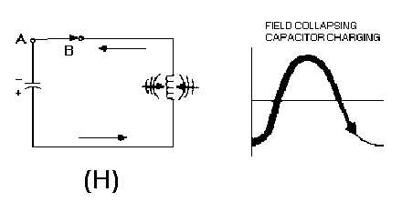
In view (H), with the capacitor completely discharged, the magnetic field again starts collapsing. The
induced voltage from the coil maintains current flowing toward the upper plate of the capacitor.
Figure 1-8H.—Capacitor and inductor action in a tank circuit.
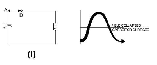
In view (I), by the time the magnetic field has completely collapsed, the capacitor is again charged
with the same polarity as it had in view (A). The energy is again stored in the capacitor, and the cycle is
ready to start again.
Figure 1-8I.—Capacitor and inductor action in a tank circuit.
The number of times per second that these events in figure 1-8 take place is called NATURAL
FREQUENCY or RESONANT FREQUENCY of the circuit. Such a circuit is said to oscillate at its
resonant frequency.
It might seem that these oscillations could go on forever. You know better, however, if you apply
what you have already learned about electric circuits.
This circuit, as all others, has some resistance. Even the relatively small resistance of the coil and the
connecting wires cause energy to be dissipated in the form of heat (I2R loss). The heat loss in the circuit
resistance causes the charge on the capacitor to be less for each subsequent cycle. The result is a
DAMPED WAVE, as shown in figure 1-9. The charging and discharging action will continue until all of
the energy has been radiated or dissipated as heat.