1-16
How the Parallel-LC Circuit Stores Energy
A parallel-LC circuit is often called a TANK CIRCUIT because it can store energy much as a tank
stores liquid. It has the ability to take energy fed to it from a power source, store this energy alternately in
the inductor and capacitor, and produce an output which is a continuous a.c. wave. You can understand
how this is accomplished by carefully studying the sequence of events shown in figure 1-8. You must
thoroughly understand the capacitor and inductor action in this figure before you proceed further in the
study of parallel-resonant circuits.
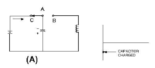
In each view of figure 1-8, the waveform is of the charging and discharging CAPACITOR
VOLTAGE. In view (A), the switch has been moved to position C. The d.c. voltage is applied across the
capacitor, and the capacitor charges to the potential of the battery.
Figure 1-8A.—Capacitor and inductor action in a tank circuit.
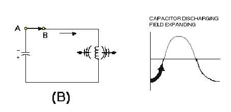
In view (B), moving the switch to the right completes the circuit from the capacitor to the inductor
and places the inductor in series with the capacitor. This furnishes a path for the excess electrons on the
upper plate of the capacitor to flow to the lower plate, and thus starts neutralizing the capacitor charge. As
these electrons flow through the coil, a magnetic field is built up around the coil. The energy which was
first stored by the electrostatic field of the capacitor is now stored in the electromagnetic field of the
inductor.
Figure 1-8B.—Capacitor and inductor action in a tank circuit.