1-29
BANDWIDTH
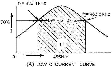
If circuit Q is low, the gain of the circuit at resonance is relatively small. The circuit does not
discriminate sharply (reject the unwanted frequencies) between the resonant frequency and the
frequencies on either side of resonance, as shown by the curve in figure 1-12, view (A). The range of
frequencies included between the two frequencies (426.4 kHz and 483.6 kHz in this example) at which
the current drops to 70 percent of its maximum value at resonance is called the BANDWIDTH of the
circuit.
Figure 1-12A.—Bandwidth for high- and low-Q series circuit. LOW Q CURRENT CURVE.
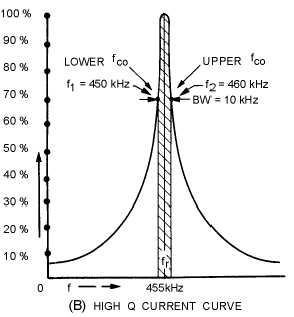
Figure 1-12B.—Bandwidth for high- and low-Q series circuit. HIGH Q CURRENT CURVE.
It is often necessary to state the band of frequencies that a circuit will pass. The following standard
has been set up: the limiting frequencies are those at either side of resonance at which the curve falls to a
point of .707 (approximately 70 percent) of the maximum value. This point is called the HALF-POWER
point. Note that in figure 1-12, the series-resonant circuit has two half-power points, one above and one


