1-30
below the resonant frequency point. The two points are designated upper frequency cutoff (fco) and lower
frequency cutoff (fco) or simply f1 and f2. The range of frequencies between these two points comprises
the bandwidth. Views (A) and (B) of figure 1-12 illustrate the bandwidths for low- and high-Q resonant
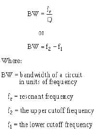
circuits. The bandwidth may be determined by use of the following formulas:
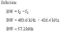
For example, by applying the formula we can determine the bandwidth for the curve shown in figure
1-12, view (A).
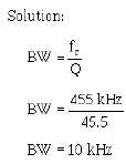
If the Q of the circuit represented by the curve in figure 1-12, view (B), is 45.5, what would be the
bandwidth?
If Q equals 7.95 for the low-Q circuit as in view (A) of figure 1-12, we can check our original
calculation of the bandwidth.