1-10
THE IDEAL SERIES-RESONANT CIRCUIT
The ideal series-resonant circuit contains no resistance; it consists of only inductance and
capacitance in series with each other and with the source voltage. In this respect, it has the same
characteristics of the series circuits you have studied previously. Remember that current is the same in all
parts of a series circuit because there is only one path for current.
Each LC circuit responds differently to different input frequencies. In the following paragraphs, we
will analyze what happens internally in a series-LC circuit when frequencies at resonance, below
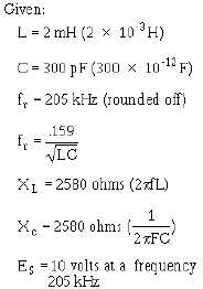
resonance, and above resonance are applied. The L and C values in the circuit are those used in the
problem just studied under resonant-frequency. The frequencies applied are the three inputs from figure
1-6. Note that the resonant frequency of each of these components is 205 kHz, as figured in the problem.
Figure 1-6.—Output of the resonant circuit.
How the Ideal Series-LC Circuit Responds to the Resonant Frequency (205 kHz)
Note: You are given the values of XL, X
C, and fr but you can apply the formulas to figure them. The
values given are rounded off to make it easier to analyze the circuit.
First, note that XL and XC are equal. This shows that the circuit is resonant to the applied frequency
of 205 kHz. XL and XC are opposite in effect; therefore, they subtract to zero. (2580 ohms
-
2580 ohms =
zero.) At resonance, then, X = zero. In our theoretically perfect circuit with zero resistance and zero
reactance, the total opposition to current (Z) must also be zero.


