1-56
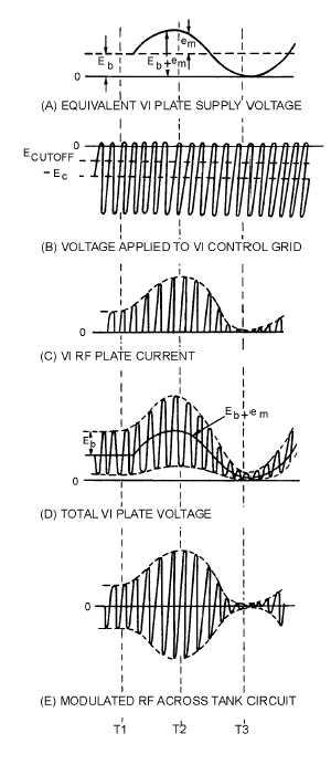
Figure 1-46.—Plate-modulator waveforms.
The rf power amplifier (V1) acts as a class C amplifier when no modulation is present in the plate
circuit. V2 is the modulator which transfers the modulating voltage to the plate circuit of V1. Let's see
how this circuit produces a modulated rf output.
View (A) of figure 1-46 shows the plate supply voltage for V1 as a constant dc value (Eb) at time 1
with no modulating signal applied. V1 is biased at cutoff at this time. The incoming rf carrier [view (A)]
is applied to the grid of V1 by transformer T1 and causes the plate circuit current to PULSE (SURGE)

