1-61
modulator varies the voltage of the cathode to produce the modulation envelope. Since the cathode is in
series with the grid and plate circuits, you should be able see that changing the cathode voltage will
effectively change the voltage of the other tube elements. By properly controlling the voltages on the
tube, you can cause the cathode modulator to operate in a form of plate modulation with high efficiency.
Usually, the cathode modulator is designed to perform about midway between plate and grid modulator
levels, using the advantages of each type. When operated between the two levels, the modulator provides
a more linear output with moderate efficiency and a modest audio power requirement.
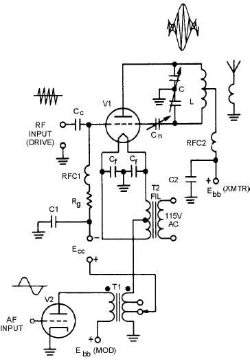
In figure 1-50, the rf carrier is applied to the grid of V1 and the modulating signal is applied in series
with the cathode through T1. Since the modulating signal is effectively in series with the grid and plate
voltage, the level of modulating voltage required will be determined by the relationships of the three
voltages. The modulation takes place in the plate circuit with the plate tank developing the modulation
envelope, just as it did in the plate modulator.
Figure 1-50.—Cathode modulator.
Emitter-Injection Modulator
This is the transistor equivalent of the cathode modulator. The EMITTER-INJECTION
MODULATOR has the same characteristics as the base-injection modulator discussed earlier. It is an


