1-58
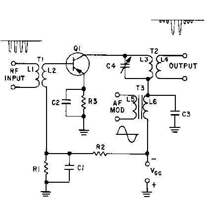
Figure 1-47.—Collector-injection modulator.
In figure 1-47, the rf carrier is applied to the base of modulator Q1. The modulating signal is applied
to the collector in series with the collector supply voltage through T3. The output is then taken from the
secondary of T2. With no modulating signal, Q1 acts as an rf amplifier for the carrier frequency. When
the modulation signal is applied, it adds to or subtracts from the collector supply voltage. This causes the
rf current pulses of the collector to vary in amplitude with the collector supply voltage. These collector
current pulses cause oscillations in the tank circuit (C4 and the primary of T2). The tank circuit is tuned to
the carrier frequency. During periods when the collector current is high, the tank circuit oscillates
strongly. At times when the collector current is small, or entirely absent, little or no energy is supplied to
the tank and oscillations become weak or die out. Thus, the modulation envelope is developed as it was in
a plate modulator.
As transistor technology continues to develop, higher power applications of transistor collector-
injection modulation will be employed. Plate and collector-injection modulation are the most commonly
used types of modulation because the modulating signal can be applied in the final stages of rf
amplification. This allows the majority of the rf amplifier stages to be operated class C for maximum
efficiency. The plate and collector-injection modulators also require large amounts of af modulating
power since the modulator stage must supply the power contained in the sidebands.
Q-40. For what class of operation is the final rf power amplifier of a plate-modulator circuit biased?
Q-41. The modulator is required to be what kind of a circuit stage in a plate modulator?
Q-42. How much must the fpa plate current vary to produce 100-percent modulation in a plate
modulator?


