1-60
while maintaining minimum distortion. The power to develop the modulation envelope comes from the rf
amplifier. Because the rf amplifier has to be capable of supplying this additional power, it is biased for
(and driven by the carrier frequency at) a much lower output level than its rating. This reduced efficiency
is necessary during nonmodulated periods to provide the tube with the power to develop the sidebands.
Compared to plate modulation, grid modulation is less efficient, produces more distortion, and
requires the rf power amplifier to supply all the power in the output signal. Grid modulation has the
advantage of not requiring much power from the modulator.
Base-Injection Modulator
The BASE-INJECTION MODULATOR is similar to the control-grid modulator in electron-tube
circuits. It is used to produce low-level modulation in equipment operating at very low power levels.
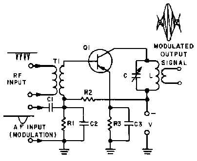
In figure 1-49, the bias on Q1 is established by the voltage divider R1 and R2. With the rf carrier
input at T1, and no modulating signal, the circuit acts as a standard rf amplifier. When a modulating
signal is injected through C1, it develops a voltage across R1 that adds to or subtracts from the bias on
Q1. This change in bias changes the gain of Q1, causing more or less energy to be supplied to the
collector tank circuit. The tank circuit develops the modulation envelope as the rf frequency and af
modulating frequency are mixed in the collector circuit. Again, this action is identical to that in the plate
modulator.
Figure 1-49.—Base-injection modulator.
Because of the extremely low-level signals required to produce modulation, the base-injection
modulator is well suited for use in small, portable equipment, such as "walkie-talkies," and test
equipment.
Cathode Modulator
Another low-level modulator, the CATHODE MODULATOR, is generally employed where the
audio power is limited and distortion of the grid-modulated circuit cannot be allowed. The cathode


