1-52
During the first 1/8 of a second (T1 to T2), the carrier wave completes exactly 1 cycle, or 360
degrees, as shown in view (C). The upper sideband, which has a frequency of 9 hertz, will complete each
cycle in less than 1/8 of a second. Therefore, during the time required for the carrier to complete 1 cycle
of 360 degrees, the upper sideband [view (B)] is able to complete 1 cycle of 360 degrees plus an
additional 45 degrees of the next cycle, for a total of 405 degrees.
The lower sideband [view (D)] has a frequency of 7 hertz and cannot complete an entire cycle in 1/8
of a second. During the time interval required for the carrier wave to progress through 360 degrees, the
lower sideband frequency of 7 hertz can complete only 315 degrees, 45 degrees short of a full cycle.
Keeping these factors in mind, you should be able to see that the phase angles between the two
sideband frequencies, and between each sideband frequency and the carrier frequency, will continually
shift. At an instant in time (T3), the carrier and sidebands will be in phase [view (E)], causing the
envelope amplitude [view (F)] to be twice the amplitude of the carrier. At another instant in time (T7), the
sidebands are out of phase with the carrier [view (E)], causing complete cancellation of the rf voltage.
The envelope amplitude will become 0 at this point. You should see that, although the carrier and
sideband frequencies have constant amplitudes, the ever-changing phase differences between them causes
the modulation envelope to vary continuously in amplitude.
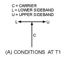
The vector analysis of the modulation envelope will be developed with the aid of figure 1-44. In
figure 1-44, view (A), a vertical vector (C) has been drawn to represent the carrier wave in figure 1-43. At
T1 in figure 1-43, the upper and lower sideband frequencies are of opposite phase with respect to each
other, and 90 degrees out of phase with respect to the carrier. This condition is illustrated in figure 1-44,
view (A), by sideband vectors U and L drawn in opposite directions along the horizontal axis. Since the
upper sideband U is equal in amplitude but opposite in phase to lower sideband L, the two sideband
voltages cancel one another; the amplitude of the envelope at T1 is equal to the amplitude of the carrier.
The same vector diagram is shown on a smaller scale in figure 1-43, view (E).
Figure 1-44A.—Vector diagrams for T1 and T2.
During the 1/8 of a second time interval between T1 and T2, all three vectors rotate in a
counterclockwise direction at a velocity determined by their respective frequencies. The vector
representing the carrier, for example, has made one complete rotation of 360 degrees and is back in its
original position, as shown in figure 1-44, view (B). The upper sideband frequency, however, will
complete 405 degrees in this same 1/8 of a second. Notice in view (B) that vector U has made one
complete counterclockwise rotation of 360 degrees, plus an additional 45 degrees for a total rotation of


