1-51
frequencies in the composite envelope. In the following analysis, vectors will be scaled to indicate the
peak voltage value of the frequencies they represent.
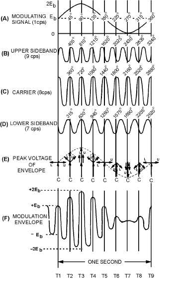
The analysis has been simplified further by using a frequency of 8 hertz to represent the carrier
frequency. Each cycle of the carrier then requires 1/8 of a second to complete 360 degrees. The carrier
will be 100-percent modulated by a sine wave having a frequency of 1 hertz, thereby producing sideband
frequencies of 7 and 9 hertz.
Envelope Development from Vectors.—The modulating signal, upper sideband, carrier, and lower
sideband waveforms are illustrated in views (A) through (D), respectively, in figure 1-43. Notice that the
vertical lines passing through the figure divide each waveform into segments of 1/8 of a second each.
These lines also coincide with the starting and ending points of each cycle of the carrier wave.
Figure 1-43.—Formation of the modulation envelope by the addition of vectors representing the carrier and
sidebands.


