1-46
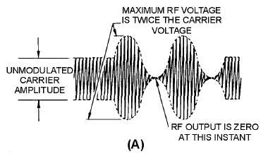
Figure 1-40A.—Conditions for 100-percent modulation.
When analyzed, the modulation envelope consists of the unmodulated rf carrier voltage plus the
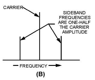
combined voltage of the two sidebands. The combined sideband voltages are approximately equal to the
rf carrier voltage since each sideband frequency contains one-half the carrier voltage, as shown in view
(B). This condition is known as 100-percent modulation and the maximum modulated rf voltage is twice
the carrier voltage. The audio-modulating voltage can be increased beyond the amount required to
produce 100-percent modulation. When this happens, the negative peak of the modulating signal becomes
larger in amplitude than the dc plate-supply voltage to the final power amplifier. This causes the final
plate voltage to be negative for a short period of time near the negative peak of the modulating signal. For
the duration of the negative plate voltage, no rf energy is developed across the plate tank circuit and the rf
output voltage remains at 0, as shown in figure 1-41, view (A).
Figure 1-40B.—Conditions for 100-percent modulation.


