1-49
By using the correct equation, you can determine the percent of modulation from the modulation
envelope pattern. This method is useful when the percent of modulation is to be determined using the
pattern on the screen of an oscilloscope. For example, assume that your oscilloscope is connected to the
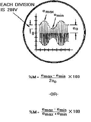
output of a modulator circuit and produces the screen pattern shown in figure 1-42. According to the
setting of the calibration control, each large division on the vertical scale is equal to 200 volts. By using
this scale, you can see that the peak carrier amplitude (unmodulated portion) is 400 volts. The peak
amplitude of the carrier is designated as eo in figure 1-42.
Figure 1-42.—Computing percent of modulation from the modulation envelope.
The amplitude of the audio-modulating voltage can also be determined from amplitude variations in
the envelope pattern. Notice that the peak-to-peak variations in envelope amplitude (emax
-
e
min) is equal
to 400 volts on the scale. Note then that the peak amplitude of the audio voltage is 200 volts. If these rf
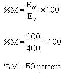
and audio voltage values are inserted into the equation, the pattern in figure 1-42 is found to represent
50-percent modulation.