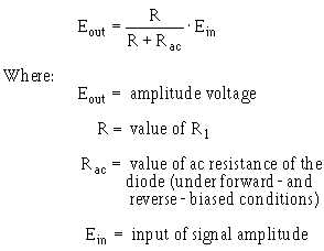
4-11
PARALLEL-POSITIVE LIMITER WITH BIAS.—Figure 4-10, view (A), shows the schematic
diagram of a PARALLEL-POSITIVE LIMITER WITH NEGATIVE BIAS. The diode is forward biased
and conducts without an input signal. D1 is essentially a short circuit. The voltage at the output terminals
is -4 volts.
Figure 4-10A.—Parallel limiter with negative bias.
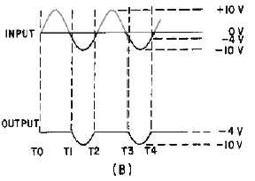
Figure 4-10B.—Parallel limiter with negative bias.
As the positive alternation of the input signal is applied to the circuit, the diode remains forward
biased and limits the entire positive alternation, as shown in view (B). As the signal goes in a negative
direction Oust before T1), the diode remains forward biased (limiting is still present) until the input signal


