4-15
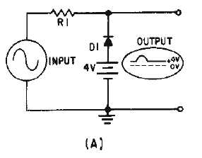
Figure 4-14A.—Parallel-negative limiter with positive bias.
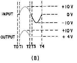
Figure 4-14B.—Parallel-negative limiter with positive bias.
Q4. What component is in parallel with the output in a parallel limiter?
Q5. What is the condition of the diode in a series limiter when an output is developed? In a parallel
limiter?
DUAL-DIODE LIMITER
The last type of limiter to be discussed in this chapter is the DUAL-DIODE LIMITER, shown in
figure 4-15, view (A). This limiter combines a parallel-negative limiter with negative bias (D1 and B1)
and a parallel-positive limiter with positive bias (D2 and B2). Parts of both the positive and negative
alternations are removed in this circuit. Each battery aids the reverse bias of the diode in its circuit; the
circuit has no current flow with no input signal. When the input signal is below the value of the biasing
batteries, both D1 and D2 are reverse biased. With D1 and D2 reverse biased, the output follows the
input. When the input signal becomes more positive than +20 volts (view (B)), D2 conducts and limits the
output to +20 volts. When the input signal becomes more negative than
-
20 volts, D1 conducts and limits
the output to this, value. When neither diode conducts, the output follows the input waveform.


