4-13
This circuit is called a parallel-positive limiter with positive bias because limiting takes place in the
positive alternation and positive bias is used on the diode.
Parallel-Negative Limiter
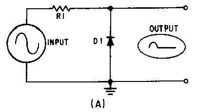
A PARALLEL-NEGATIVE LIMITER is shown in view (A) of figure 4-12. Notice the similarity of
the parallel-negative limiter and the parallel-positive limiter shown in view (A) of figure 4-9. From T0 to
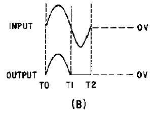
T1 of the input signal, the diode is reverse biased and does not conduct, as shown in view (B) of figure
4-12. The output signal follows the input signal and the positive alternation is not limited.
Figure 4-12A.—Parallel-negative limiter.
Figure 4-12B.—Parallel-negative limiter.
During the negative alternation of the input signal (T1 to T2), the diode is forward biased and
conducts. The relatively low forward bias of D1 develops a very small voltage and, therefore, limits the
output to nearly 0 volts. A voltage is developed across the resistor as current flows through the resistor
and diode.


