4-12
exceeds
-
4 volts (T1). D1 becomes reverse biased as the anode becomes more negative than the cathode.
While the input signal is more negative than the
-
4 volts of the bias battery (T1 to T2), the diode is
reverse biased and remains cut off. The output follows the input signal from T1 to T2. At all other times
during that cycle, the diode is forward biased and limiting occurs. This circuit is called a parallel-positive
limiter with negative bias because the positive output is limited and the bias in the circuit is negative with
reference to ground. Limiting takes place at all points more positive than
-
4 volts.
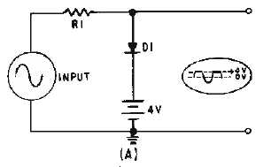
The circuit shown in figure 4-11, view (A), is a PARALLEL-POSITIVE LIMITER WITH
POSITIVE BIAS. The positive terminal of the battery is connected to the cathode of the diode. This
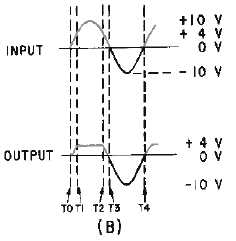
causes the diode to be reverse biased at all times except when the input signal is more positive than the
bias voltage (T1 to T2), as shown in view (B).
Figure 4-11A.—Parallel-positive Limiter with positive bias.
Figure 4-11B.—Parallel-positive Limiter with positive bias.
As the positive alternation of the input signal is applied (T0), the output voltage follows the input
signal. From T1 to T2 the input signal is more positive than + 4 volts. The diode is forward biased and
conducts. At this time the output voltage equals the bias voltage and limiting takes place. From T2 to T4
of the input signal, the diode is reverse biased and does not conduct. The output signal follows the input
signal and no limiting takes place.


