4-10
Parallel-Positive Limiter.
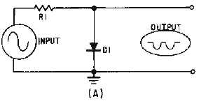
The schematic diagram shown in figure 4-9, view (A), is a PARALLEL-POSITIVE LIMITER. The
diode is in parallel with the output and only the positive half cycle of the input is limited. When the
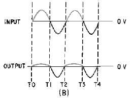
positive alternation of the input signal is applied to the circuit (T0 to T1), the diode is forward biased and
conducts. This action may be seen in view (B). As current flows up through the diode and the resistor, a
voltage is dropped across each. Since R1 is much larger than the forward resistance of D1, most of the
input signal is developed across R1. This leaves only a very small voltage across the diode (output). The
positive alternation of the input signal has been limited.
Figure 4-9A.—Parallel-positive limiter.
Figure 4-9B.—Parallel-positive limiter.
From T1 to T2 the diode is reverse biased and acts as an extremely high resistance. The negative
alternation of the input signal appears across the diode at approximately the same amplitude as the input.
The negative alternation of the input is not limited.
As with the series limiter, the parallel limiter should provide maximum output voltage for the
unlimited part of the signal. The reverse-bias resistance of the diode must be very large compared to the
series resistor. To determine the output amplitude, use the following formula:


