4-14
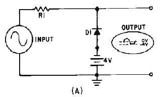
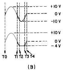
PARALLEL-NEGATIVE LIMITER WITH BIAS.—The circuit shown in figure 4-13, view (A),
is a parallel-negative limiter with negative bias. With no input, the battery maintains D1 in a reverse-bias
condition. D1 cannot conduct until its cathode is more negative than its anode. D1 acts as an open until
the input signal dips below
-
4 volts at T2 in view (B). At T2 the input signal becomes negative enough to
forward bias the diode, D1 conducts and acts like a short, and the output is limited to the
-
4 volts from
the battery from T2 to T3. Between T3 and T4 the diode is again reverse biased. The output signal
follows the input signal and no limiting occurs.
Figure 4-13A.—Parallel-negative limiter with negative bias.
Figure 4-13B.—Parallel-negative limiter with negative bias.
Figure 4-14, view (A), shows a parallel-negative limiter with positive bias. The operation is similar
to those circuits already explained. Limiting occurs when the diode conducts. No limiting occurs when
the diode is reverse biased. In this circuit, the bias battery provides forward bias to the diode without an
input signal. The output is at +4 volts, except where the input goes above +4 volts (T1 to T2), as shown in
view (B). The parts of the signal more negative than +4 volts are limited.


