3-22
Figure 3-27.—Flip-flop with trigger pulse on SET and inputs.
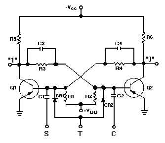
Some flip-flops use a third input lead, as shown in figure 3-28. This third input lead is called a
TOGGLE (T) input. Every time a pulse is applied to the T input, the flip-flop will change states from
whatever its state was previously. The two diodes (CR1, CR2) form a STEERING NETWORK. This
steering network directs a positive input pulse to the saturated transistor, causing it to cut off. Negative
pulses are blocked by the diodes. Note that if npn transistors were used, the diodes would have to be
reversed and the TOGGLE signal would have to be negative. For example, assume that Q1 is saturated,
Q2 is cut off, and a positive pulse is applied the at T input. The input pulse will be directed to both
transistors. The positive pulse will not affect Q2 since it is already in cutoff. Q1 however, which is
conducting, will cut off and will cause Q2 to become saturated. The transistors have reversed states. A
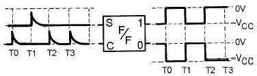
block diagram which represents a multivibrator and its outputs with only a TOGGLE input signal is
shown in figure 3-29. Studying this figure should help you understand how this flip-flop works. Each
TOGGLE input causes the output to change states. Figure 3-30 shows what happens when triggers are
applied to all three inputs of the flip-flop shown in figure 3-28. Assume that the flip-flop in figure 3-30 is
in the CLEAR state ("1" output is 0 volts, "0" output is high) prior to T0. At T0 a trigger is applied to the
set input and the flip-flop changes states. Next, the CLEAR input is triggered and the flip-flop returns to
the CLEAR state at T1. A TOGGLE at T2 causes the flip-flop to change state, so it is once again SET.
Another TOGGLE changes the flip-flop to the CLEAR state at T3 (notice that TOGGLE triggers flip the
multivibrator regardless of its previous state). Now, a SET input trigger at T4 sets the flip-flop. The
CLEAR input pulse at T5 causes the circuit to CLEAR, and the CLEAR input at T6 has no effect on the
flip-flop, for it is already in the CLEAR state.
Figure 3-28.—Flip-flop with three inputs.