3-21
So far, the basic flip-flop has used only pnp transistors. It could have just as easily used npn
transistors. The functional operation would not change; only the polarities required for conduction and
cutoff change. As a technician, you may see either type of transistor used, npn or pnp. A symbolic block
diagram is sometimes used to avoid confusion about voltage polarities.
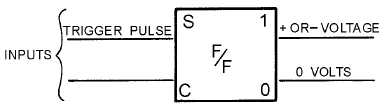
A special kind of block diagram has been adopted as a standard symbol for the flip-flop and is shown
in figures 3-25 and 3-26. The two inputs are represented by the lines on the left and the outputs by the
lines on the right. INPUTS to a flip-flop are S (SET) and C (CLEAR) and OUTPUTS from a flip-flop are
"1" and "0." A trigger pulse applied to the SET input causes the "1" output to be a positive or negative
voltage, depending on the type of transistor. At the same time, the "0" output equals 0 volts. This
condition is called the SET STATE.
Figure 3-25.—Flip-flop (SET state).
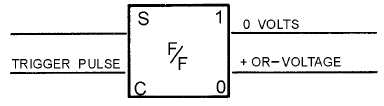
Figure 3-26.—Flip-flop (CLEAR state).
If a trigger pulse is applied to the CLEAR input, a positive or negative voltage is produced at the "0"
output. The "1" output goes to 0 volts. This condition is called the CLEAR STATE, as shown in figure
3-26.
To determine what state the flip-flop is in, you can measure either the "1" or the "0" output.
Measuring 0 volts at the "1" output indicates that the flip-flop is in the CLEAR state. If the "0" output is
measured, a positive or negative voltage would also indicate that the flip-flop is in the CLEAR state.
Either way, only one reading is necessary.
In figure 3-27, the flip-flop is in the SET state prior to T0 (negative voltage on the "1" output). Now
compare the changes in output voltage at each point in time (T0, T1, T2, and T3) with the input pulse.
Studying this figure should help you understand how the flip-flop works. The positive pulse at T0 on the
CLEAR input shifts the f/f to the CLEAR state (negative voltage at the "0" output). At T1 a positive pulse
on the SET input drives the "1" output to the SET state. At T2 a positive pulse on the CLEAR input drives
the "0" output to a CLEAR state. At T3 another positive pulse is applied to the CLEAR input. This input
has no effect since the f/f is already in the CLEAR state.