3-18
Two voltage-divider networks extend from -10 volts (V
CC) to +6 volts (VBB). One voltage divider
consisting of resistors R1, R4, and R6 supplies the bias voltage to the base of Q1. The other voltage
divider consists of R2, R3, and R5 and supplies the bias voltage to the base of Q2.
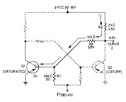
Assume that Q1 (figure 3-20) is initially saturated and Q2 is cut off. Recall that the voltage drop
from the base to the emitter of a saturated transistor is essentially 0 volts. In effect, this places the base of
Q1 at ground potential. The voltages developed in the voltage divider,
-
VCC, R6, R4, R1, and +VBB, are
shown in the figure.
Figure 3-20.—Flip-flop (Q1 voltage divider).
Since no current flows through Q2, very little voltage is dropped across R6 (approximately 0.5 volt).
The voltage at output 2 would measure -9.5 volts to ground (approximately
-
VCC).
This voltage (
-
9.5 volts) is considered to be a HIGH output. Figure 3-21 shows the values of the
other voltage-divider network.