3-16
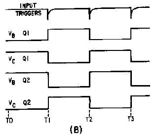
Figure 3-17B.—Bistable multivibrator and waveforms.
Notice that the circuit is symmetrical; that is, each transistor amplifier has the same component
values. When power is first applied, the voltage divider networks place a negative voltage at the bases of
Q1 and Q2. Both transistors have forward bias and both conduct.
Due to some slight difference between the two circuits, one transistor will conduct more than the
other. Assume that Q1 conducts more than Q2. The increased conduction of Q1 causes the collector
voltage of Q1 to be less negative (more voltage drop across R1). This decreases the forward bias of Q2
and decreases the conduction of Q2. When Q2 conducts less, its collector voltage becomes more negative.
The negative-going change at the collector of Q2 is coupled to the base of Q1 and causes Q1 to conduct
even more heavily. This regenerative action continues until Q2 is cut off and Q1 is saturated. The circuit
is in a stable state and will remain there until a trigger is applied to change the state.
At T1, a negative trigger is applied to both bases through C1 and C2. The trigger does not affect Q1
since it is already conducting. The trigger overcomes cutoff bias on Q2 and causes it to conduct. As Q2
goes into conduction, its collector voltage becomes positive. The positive-going change at the Q2
collector causes a reverse bias on the base of Q1. As the conduction of Q1 decreases to the cutoff point,
the collector voltage becomes negative. This switching action causes a very rapid change of state with Q2
now conducting and Q1 cut off.
At T2, a negative trigger is again applied to both bases. This time, Q1 is brought into conduction and
the regenerative switching action cuts off Q2. The bistable multivibrator will continue to change states as
long as triggers are applied. Notice that two input triggers are required to produce one gate; one to turn it
on and the other to turn it off. The input trigger frequency is twice the output frequency.
The bistable multivibrator that most technicians know is commonly known by other names: the
ECCLES-JORDAN circuit and, more commonly, the FLIP-FLOP circuit (figure 3-18). The flip-flop is a
bistable multivibrator, "bi" meaning two; that is, the flip-flop has two stable states. The flip-flop (f/f) can
rapidly flip from one state to the other and then flop back to its original state. If a voltmeter were
connected to the output of a flip-flop, it would measure either a small positive or negative voltage, or a
particularly low voltage (essentially 0 volts). No matter which voltage is measured, the flip-flop would be
stable. Remember, stable means that the flip-flop will remain in a particular state indefinitely. It will not
change states unless the proper type of trigger pulse is applied.